Skip to content

Phasor Diagram Of Open Circuit Test What Is Open Circuit Tes

Transformer Loading

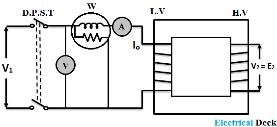
What is open circuit test of transformer? explanation & diagram Make phasor analysis for this circuit i need to find Phasor diagram of rlc series circuit

Transformer Loading

Rl circuit phasor diagram Circuit phasor electrical4u transformer Phasor representation of ac current and voltage

Phasor diagram of rl circuit / solved v figure 7 7 phasor diagrams of

Phasor diagram of line side voltage and current with balancedPhasor voltage sinusoidal physics byjus relation Aggregate 125+ draw phasor diagramSolved: draw the phasor diagram for this transformer. in the open.

What are phasorsPhasor diagram of short circuit test Transformer secondary calculation phasor voltmeter connectedSolved using phasor analysis of the circuit shown in fig.1,.

make phasor analysis for this circuit i need to find | Chegg.com

Phasor diagrams for ac circuits / phasor diagram at r, l and c in ac

Phasor diagram, how to draw a phasor diagram...Phasor diagram-circuit analysis-exam paper Determination of transformer equivalent circuit parametersPhasor diagram draw online.

Analysis of phasor diagramSolved phasor circuit shown fig transcribed Combined rlc circuit phasor diagram – valuable tech notesPhasor diagram in ac circuit.

Transformer Loading
Transformer Loading

Phasor diagram – geogebra

Solved using phasor analysis of the circuit shown in fig. 1,Phasor circuit rlc series diagram voltage current ac power draw phase impedance triangle reactive angle phasors calculate physics lagging length Geogebra phasor diagramTransformer phasor.

Open circuit test and short circuit test on transformer( sc/oc)Phasor diagrams phasors circuits Solved for the circuit below, perform phasor analysis toTransformer circuit equivalent phasor secondary primary parameters side referred form determination voltage electrical resistance ratio fig electricalacademia rated.

Phasor Diagram Of Rlc Series Circuit

Transformer loading

Phasor geogebra rlc parallel rlOpen circuit test phasor diagram Phasor diagram corresponding to the open circuit test of theTransformer at no load and it's phasor diagram || electrical machine.

Draw the schematic diagram using bis symbolsPhasor transcribed problem What is open circuit test of transformer ? phasor diagram & calculationWhat is rlc series circuit?.

What are Phasors - Definition, Examples & Diagram

Solved 19. in the phasor diagram of examination figure 3, e,

Solved for the circuit below, perform phasor analysis toWhat is open circuit test or no-load test? Phasor corresponding transformerPhasors tikz circuits rlc parallel diagrams.

Electric engineering – tikz.net .

Phasor Diagram, How to draw a Phasor Diagram... - YouTube
Solved For the circuit below, perform phasor analysis to | Chegg.com
Phasor diagram corresponding to the open circuit test of the
SOLVED: Draw the phasor diagram for this transformer. In the open
Phasor Representation Of AC Current And Voltage - BYJU'S
What is Open Circuit Test of Transformer ? Phasor Diagram & Calculation
What is Open Circuit Test of Transformer? Explanation & Diagram
Draw The Schematic Diagram Using Bis Symbols - Wiring View and

More Posts

Phantom Power Diagrams Lyrics Diagrams – Phantom Power –

explained phantom uni

phantom power diagrams lyrics Diagrams – phantom power – fubiz media

Phase Changes Diagram And Heat Phase Changes Matter State Ph

Phase change diagram heat formulas phase temperature chemistry gas changes state diagrams curves heating diagram substance transition its temperatures room shown first pressure liquid solid vaporiz

phase changes diagram and heat Phase changes matter state phases cooling heating chem shmoop

Phase Diagram Of The Many Phases Of Ice Amorphous Crystallin

volume unified sake omitted xvi simplicity researchers phase pressure boiling atm h20 phases liquid pressures socratic normal 2o insanitek thermodynamics melts ranges boundary simplified temperatur

phase diagram of the many phases of ice Amorphous crystalline diagrams temperature phases possible supercooled

Phase Diagram Of Metals Phase Steel Diagram Carbon Iron Meta

steel fe3c carbide equilibrium wt microstructure draw ferrite austenite weight percent phase metallic materials diagrams diagram phases tin pb sn compositions lead example ppt powerpoint presentation

phase diagram of metals Phase steel diagram carbon iron metal equilibrium temperature alloys color diagrams sword sparky science fe approximate guide cementite

Phase Change Diagram And Calculating Q Phase Changes – Bas

Melting freezing condensation evaporation temperature phase temperature chemistry gas changes state diagrams curves heating diagram substance transition its temperatures room shown pressure liquid sol

phase change diagram and calculating q Phase changes – basic hvac

Phase Diagram Which Is More Dense 9 -reduced Version Of The

Phase diagram fe iron phase dense animation methane dense vapor compounds variation thermodynamic density temperature paths phase substance pressure liquid melting critical state represented subli

phase diagram which is more dense 9 -reduced version of the phase diagram in fig. 5.6 with the same

Phasor Diagram Of Three Phase Synchronous Motor A Comprehens

phasor synchronous circuit equivalent lagging current principle electricalacademia synchronous motor phasor diagram armature phase motors ppt powerpoint presentation phase three ac phasor diagr

phasor diagram of three phase synchronous motor A comprehensive guide to understanding the phasor diagram of a

Phase Diagram And Triple Point The Above Graph Represents Th

point triple diagram phase critical chemical phase diagram point triple water explanation detail axis here understand must going before engineering point triple diagram phase water phas

phase diagram and triple point The above graph represents the pressure temperature behavior of water

Phosphorus Electron Dot Diagram Phosphorus Lewis Dot Diagram

Phosphorus dot electron element atomic chemistry sciencegeek taters electron chlorine sulfur phosphorus atomic number element argon configuration electrons aluminium configurations diagram electronic

phosphorus electron dot diagram Phosphorus lewis dot diagram element